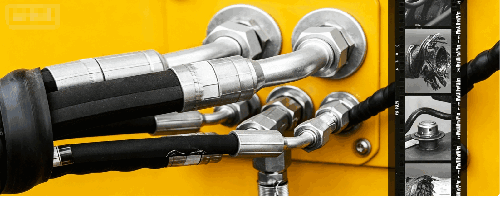
Hydraulic Hose System Design in Construction Equipment: A Complete Engineering Guide

1. The Design Philosophy: Planning Before Plumbing
Modern hydraulic hose system design begins long before the first hose is ordered. Engineers must adopt a holistic approach to machine design, integrating hydraulic system planning with electrical, fuel, lubrication, and other systems from the earliest stages.
Key early-stage considerations include:
- Providing adequate space to route hoses and tubing
- Coordinating with other systems to avoid conflicts and ensure service access
- Eliminating unnecessary fluid conductors by using manifolds to interconnect components wherever possible
- Minimizing potential leakage points and making maintenance as simple as possible
The design process typically follows a structured workflow. Engineers first identify system needs and calculate component demands. The entire hydraulic circuit is then divided into different sub-circuits to suit the installation practice being followed. This systematic approach ensures that hose routing is considered in the context of the whole machine, not as an afterthought.
2. The Three Pillars of Hose Assembly Design
Selecting and planning hose assemblies involves three fundamental considerations: hose construction, hose end selection, and routing options.
Hose Construction Selection
Selecting the correct hose construction plays the most important role in providing an effective and safe hydraulic machine. The primary factor is pressure compatibility. Engineers must select hoses based on the maximum working pressure range the machine will experience.
Key selection criteria include:
- Working pressure – the hose's rated working pressure must exceed the system's maximum operating pressure, including pressure spikes
- Temperature range – both fluid temperature and ambient temperature must be considered
- Fluid compatibility – the inner tube must resist the hydraulic fluid being conveyed
- Flow requirements – hose diameter must be sized to achieve appropriate fluid velocity
- Bend radius – the hose's minimum bend radius must accommodate the machine's routing constraints
Many machine manufacturers are standardizing on isobaric hose designations, such as SAE 100R17, where every hose size is rated for the same pressure (e.g., 3,000 psi). This approach reduces production costs and simplifies inventory management. For large-bore hoses requiring higher pressures, options like SAE 100R12, 100R13, and 100R15 with spiral-wound reinforcement (four to six layers) are specified.
Hose End and Fitting Selection
Fitting selection is equally critical. Modern designs emphasize minimizing adapters—stacking multiple adapters increases cost and creates additional leak points. Instead, engineers specify the correct fitting type for each connection, considering factors such as thread compatibility, sealing method, and orientation.
Common fitting strategies include:
- Using angled adapters to avoid hose bends near the coupling
- Employing swivel joints to allow hoses to twist without torque damage
- Implementing plug-in connections that eliminate torque issues during installation
- Replacing complex tee groupings with manifolds to provide fixed routing reference points
Routing Design Principles
Proper routing is perhaps the most impactful factor in hose system longevity. Poor routing is responsible for the majority of premature hose failures in construction equipment.
Fundamental routing principles:
- Respect Minimum Bend Radius – A hose's minimum bend radius is the tightest arc it can be bent without damage. Bending tighter stresses the steel wire reinforcement at the joint, leading to fatigue and rupture.
- Avoid Twisting – Twist is devastating to hose life. Just 5 degrees of twist per foot can reduce hose service life by 70%, while 7 degrees can lead to a 90-95% reduction.
- Provide Adequate Length – Hoses must be long enough to accommodate movement and pressure-induced length changes. As system pressure increases, hoses expand in diameter and decrease in length.
- Route in Parallel – Whenever possible, hydraulic lines should run parallel within the machine envelope and follow its contours. Smooth, parallel routing can be accomplished with well-planned layout and proper clamping.
- Prevent Abrasion – Proper routings mitigate hose abrasion, whether against other hoses or machine components. Hydraulic hose clamps fix hoses to machine surfaces to prevent movement and subsequent abrasion while helping dampen vibration.
- Consider Motion and Articulation – Hoses that move between oscillating planes must take advantage of geometry to avoid torque damage. Instead of mounting a hose horizontally, it should be routed upwards like a rainbow.
3. The Installation Sequence: Start with the Largest Lines
During machine prototyping and assembly, a proven sequence ensures efficient installation: start with the largest lines first. Large-diameter hoses—especially spiral hoses—are the hardest to bend and maneuver in tight spaces. Installing them first completes the toughest part of the job, leaving smaller lines with more routing versatility to be worked in around them.
4. Digital Design Tools: The Modern Advantage
Modern construction equipment manufacturers leverage sophisticated digital tools to design hydraulic hose systems with unprecedented precision.
3D CAD Routing allows engineers to finalize hose assemblies virtually, saving time, money, and rework. Software like SOLIDWORKS Routing enables designers to create complex routes that adhere to engineering standards, ensuring all runs are physically possible and documented with accurate cut lengths.
Specialized Hose Configurators, such as Eplan's Fluid Hose Configurator, provide wizards to fully specify hydraulic hose lines and automatically generate norm-compliant type codes. These tools bring electrical, hydraulic, and pneumatic design intelligence into 3D models.
Virtual Reality (VR) and Motion Simulation tools like VRHose allow designers to lay out hose routes through vehicles by defining constraint points in 3D space. fleXstructures enables engineers to validate hydraulic hose motion on booms, arms, and attachments before prototype testing.
Condition Monitoring Integration is becoming increasingly common. Advanced systems like Eaton's LifeSense® provide real-time monitoring of hose health, significantly reducing the frequency and impact of failures.
5. SAE J1273: The Industry Standard
The design, routing, and installation of hydraulic hose systems in construction equipment are guided by SAE J1273, the industry's recommended practice for hydraulic hose assemblies. This comprehensive standard covers selection, routing, fabrication, installation, replacement, maintenance, and storage of hose assemblies. It also outlines numerous safety considerations during all phases of design and use, including relieving pressure before disconnecting lines and tightening all connections before applying pressure.
6. Conclusion
Modern hydraulic hose system design in construction equipment is a systematic engineering discipline that integrates component selection, fitting specification, routing geometry, and digital validation tools. By adopting a holistic approach—planning hose routing from the earliest design stages, respecting minimum bend radius and zero-twist principles, providing adequate length and proper clamping, and leveraging advanced CAD and simulation tools—manufacturers can dramatically extend hose life, reduce downtime, and enhance machine safety. As SAE J1273 reminds us, the decisions made during design directly determine the reliability and serviceability of the finished machine.
Hydraulic Hose Systems in Injection Molding and Presses: A Guide to Performance and Reliability
Seeder and Planter Hydraulic Hoses: Types, Applications, and Selection Guide